Rough automatic draft, low quality: expect mistakes and awkward wording. It will be replaced by a better translation. Original →
16
SWITCHING DIAGRAMS
R. V. Freivald
At the V All-Union Mathematical Optimization*) the following problem was proposed:
A switch (Fig.1) with two inputs and two outputs can be in two different states.
figure 2 shows a telephone communication circuit with three inputs and three outputs, which has the following property of “universality”:

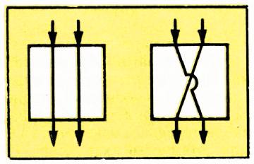
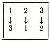
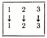
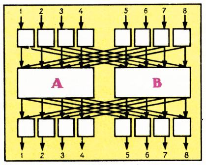
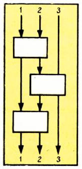
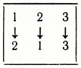
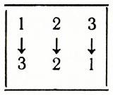
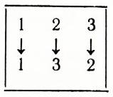
Fig. 1. Fig. 2. Fig. 3.
by changing the state of the switch, you can make any of the six connections of three inputs with three different outputs, that is
(Check this out. Note that the total number of different states of this circuit is 2³=8, since each of the switches can be in two states.)
a) Construct a circuit with four inputs and four outputs that would be “universal”, that is, any of the 24 possible connections of inputs and outputs would be implemented.
b) What is the minimum number of switches needed for such a circuit?
b) We call a circuit with n inputs and n outputs n-universal if
*) For more information about random optimization, see «Kvant» No. 11, 1971, pp. 35-42.
18
Divide into blocks and so that 4 connections pass through and 4 through . In doing so, we must ensure that two connections do not pass through the same input or the same output of blocks and .
Let’s consider the first and fifth inputs of our circuit. Each of them can be connected either to the first input of block or to the first input of block . Therefore, one of these inputs must be connected to block , the other to block , otherwise two connections will be connected to the same input of some block. The following pairs of inputs must also be connected to different blocks: 2nd and 6th, 3rd and 7th, 4th and 8th. It is easy to see that such a condition for distributing connections across blocks is not only necessary, but also sufficient to ensure that different connections in the circuit do not pass through the same input of blocks and . To form the same condition for the inputs to blocks and , it is useful to pay attention to the symmetry of the arrangement of the inputs and outputs of the circuit. We conclude that the following pairs of circuit outputs must be connected to different blocks: 1st and 5th, 2nd and 6th, 3rd and 7th, 4th and 8th.
Let us depict on figure these relationships between different connections of the same compound. Each individual connection will be represented by a rectangle, inside of which it is written which input this connection connects to which output. If two connections must pass through different blocks, then the corresponding rectangles are connected by a linear line. In this case, we will draw a linear line in red if there are 4 differences with inputs, and in blue if there are 4 differences with outputs.
For example, connection
depicted in this way on figure 7.
Whatever the connection, exactly one blue and exactly one red line emerges from each rectangle. Therefore figure always consists of one or more “rings”. Moreover, in each “ring” red and blue lines alternate, otherwise two lines of the same color would come out of a certain rectangle. Consequently, each “ring” contains a number of primogols.
Using this figure, it is easy to distribute connections among blocks so that all the above restrictions are met. To do this, you need to ensure that the connections that correspond to rectangles connected by a linear line pass through the blocks. Therefore, in each “ring” figure you need to randomly select one slug and the connection corresponding to this slug should be made through block , then the connection corresponding to the corresponding slug should be made through block , then the connection corresponding
19
shue to the next rectangular, through and so on until the “ring” is closed. The connections corresponding to the first and last rectangles will be made through different blocks, since the number of rectangles in the “ring” is even. The 8-universal scheme (see Fig. 3) has been proven. We only note that the distribution of communication across blocks can always be carried out so that one of the switches (for example, the lower left) is in some predetermined state. (In other words, this switch can be removed from the circuit, but the circuit cannot be changed to be universal.) Then, in the “ring” containing the connection passing through the selected switch, the distribution of the connection across blocks must begin with this connection.
To estimate from above the number of switches in a minimal -universal circuit, we will construct -universal circuits with as few switches as possible. The above proof of the 8-universal circuit (see Fig.3) can be easily generalized to the case of any number of inputs. This method makes it possible, having an 8-universal circuit, to build a fairly economical 16-universal circuit, then a 32-universal circuit, and so on. It can be calculated that if and the circuit (Fig. 4) is used as blocks of a 4-universal circuit, then such a circuit has switches. If is not equal to a whole power of two, then you can use a circuit that is universal for a large number of inputs equal to a full power of two. Since the closest complete power of two exceeds the given number by no more than twice, it turns out that for any there is a -universal circuit containing at most switches.
(For ending, see page 27.)