Rough automatic draft, low quality: expect mistakes and awkward wording. It will be replaced by a better translation. Original →
30
STRANGE PENDULUM
N.A. MINC
An ordinary mathematical mat, familiar to you, is no less than the plane of its oscillations.
The well-known demonstration of the rotation of the Earth, Foucault’s experiment, is based on this property of the matnik. The matnik on the long pendant oscillates. Below it is a circle that fills the dial. Due to the fact that the plane of vibration of the matnik relative to the fixed stars does not change, and the Earth rotates around its own axis, over time the matnik passes sequentially over all marks of the circle. At the pole, within 24 hours the circle under the mat will complete a full revolution. For the first time such an experiment was carried out by the French physicist L. Foucault in 1851 under the dome of the Pantheon in Paris with a 67 m long mat.
But does every motherboard necessarily maintain the plane of oscillations? After all, the suspension thread allows it to oscillate in any vertical plane.
Try to make a mat like that shown in figure 1. To do this, take a thread, fold it in half, and tie another thread to the middle. Attach a spoon, strings or some other object to the other end of this second thread - and the mat is ready. (The vertical pendant thread should be long enough. At least not less than the inclined pendant thread.)
Hang the matnik at both ends of a thread folded in half on horses or nails (for example, in a doorway). If you now open the mat from the equilibrium position and then lower it, you will see an interesting picture. The matnik will move along an ellipse, and this ellipse will constantly change, stretching in one direction or the other. Why is this happening?
For a matnik with one suspension point (Fig. 2), the oscillation plane is not highlighted. Whatever it is
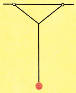
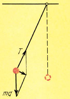
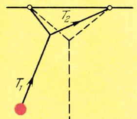
Fig. 1. Fig. 2. Fig. 3.
31
the initial deflection of the matrix, all the forces acting on it lie in the same plane. It is only necessary, when releasing the matrix, not only his choice.
Indeed, let us draw a plane through the initial and deflected positions of the matrix. Obviously, both the gravitational force and the tension force of the thread will lie in this plane. Consequently, the acting force of these forces, which, in fact, causes the matrix to oscillate, is equal; for any deflected position, the matrix also lies in the same plane. This means that there are no forces, which can be quite complex, especially at close frequencies of longitudinal and transverse vibrations. If the frequencies are the same, the motion trajectories will be an ellipse. The figure shown in Fig. 4 describes a matrix whose equation of motion is as follows: , . Figure 5 corresponds to vibrations , .
The frequency ratio can be adjusted by changing the length ratio
Of course, if the matrix is deflected in line with the primary plane of the suspension, it will oscillate in one plane, the primary plane of the suspension. But in practice there is always a deviation from the initial point and a speed that does not lie in the plane of the initial deviation.
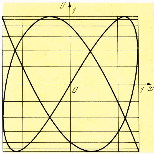
Fig. 4.
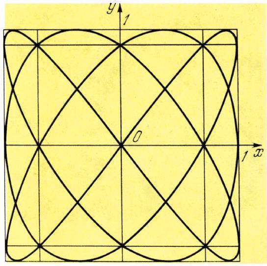
Fig. 5.
32
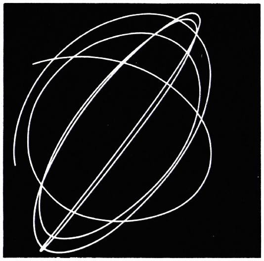
Fig. 6.
vertical and inclined suspension threads. At the same time, it is quite difficult to calculate the vibration frequencies of a magtin, but it is much easier to see the figures drawn by it.
In order to see the Lissajous figures, you can attach a bucket filled with sand to the suspension of our magtin, and put a piece of cardboard painted in a dark color on the floor. Then the magtink will “draw” a clear trajectory of its movement.
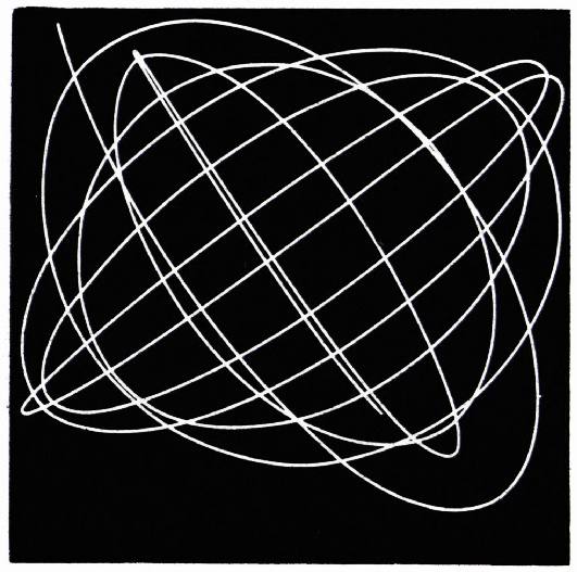
Fig. 7.
You can get a photograph of the magtin’s movement trajectories.
Take a sinker or heavy small ball and paint it white and red. Make the same pendant from dark threads as the magtinik shown in figure 1. Place a sheet of black matte paper under the magtinik. Smooth paper can cut off, and this will interfere with what is being observed. You need to take photos from above. Position the camera so that the object plane is horizontal. With a sufficiently long shutter speed, you can see clear trajectories on the photos.
Figures 6 and 7 show a photograph of the trajectories obtained in this way. It can be seen how the magnetite changed the direction of vibrations. In figure figure 6 this change will occur more sharply. The exposure time of the two photographs is different. This can be seen at least from the fact that the length of the trajectories is not the same.
The resulting curves seem to be inscribed in a parallelogram. In fact, they should be entered into a straight line. The fact that we did not get a straight line can be explained simply: the plane of the object was not strictly horizontal.
In experiments with magnetism, it should be taken into account that a more or less correct trajectory is obtained only in the case when there are no strong attenuations. The oscillations of a magnet with a small load mass and a sufficiently large volume will be damped. So magtinik qualitatively several times, quickly reducing the amplitude. Naturally, when moving with strong attenuation, it is difficult to see and photograph the change in the direction of oscillations of the magnet.
You often encounter Lissajous figures in cases where the oscillations are mutually perpendicular. So, they inevitably appear when setting up an oscilloscope.