Rough automatic draft, low quality: expect mistakes and awkward wording. It will be replaced by a better translation. Original →
42
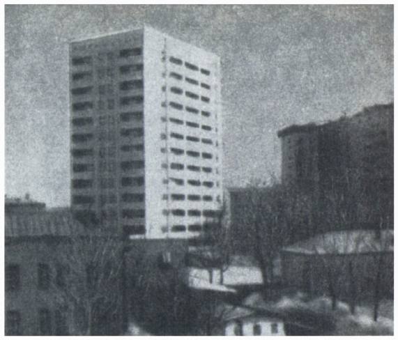
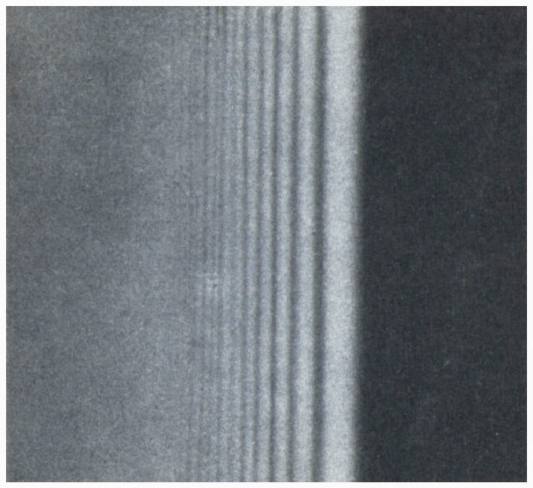
Fig. 1. Photograph taken with a Zenit camera, in which the lens was replaced by a piece of black paper with a rejection. Rejection diameter 0.2 mm, film sensitivity 65 units, shutter speed 5 sec.
Geometric optics is based on the idea of straightness of light rays. Practice teaches us this. You yourself can easily check the experiment confirming the linearity of light propagation. Replace the camera lens with a piece of black paper with a small rejection pierced into it. Such a “hole camera” (called a pinhole camera) can produce a photograph of brightly illuminated objects, similar to the photograph shown in figure 1. The image on the film exactly corresponds to the central projection of the object’s points with straight lines passing through the rejection, which is a strong argument for the idea of rays of light as straight lines.
We define the formation of a shadow on a white screen from an opaque object as a projection of the contour of the object onto the plane of the screen by rays emanating from each point of the light source. Since the light source is usually quite large, the shadow boundary is surrounded by penumbra and blurred. One might think that by reducing the size of the source, we will dry out the penumbra region and ultimately obtain a sharp shadow. However, experience shows that when the light source becomes too small, phenomena are revealed that were previously massaged by penumbra. Taking the edge of the opaque plate together with the sharp shadow gives the picture shown in figure 2. The edge of the shadow is blurred, and parallel to it are dark and light stripes of decreasing structure. If the light source is white, then the stripes are colored in rainbow colors.
The shadow from a thin wire (Fig. 3) also has a complex structure. On the outside it has stripes, like at the edge of an opaque plate, and inside the shadow there are dark and light stripes, all the narrower than just the wire.
The shadow from a ball or from a small opaque disk (Fig. 4) looks completely unexpected. In addition to the dark and light wheels surrounding the shadow and similar to the stripes already familiar to us, in the center of the shadow you can see a bright light spot, as if a small rejection had been pierced in the center of the disk.
Phenomena in which it is found
43
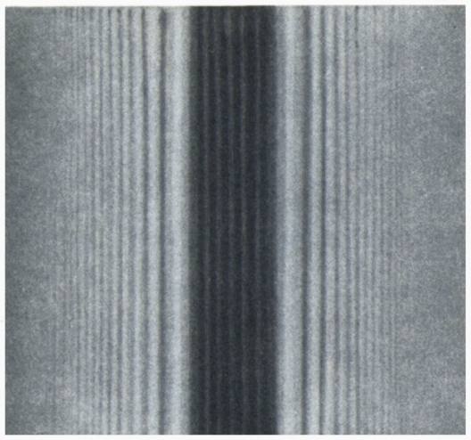
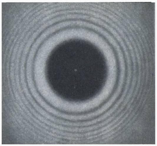
Fig. 3. Diffraction from a thin wire. Shot in white light through a red filter. Wire diameter 1.2 mm. The distance from the wire to the film is 0.5 m.
It turns out that light does not propagate according to the laws of geometric optics, called diffraction. Their reason lies in the wave nature of light. An accurate description of the propagation of light is given not by the construction of rays, but by the pattern of wave propagation.
Let’s imagine circular waves diverging from a thrown stone along the calm surface of a pond. If the waves reach a log floating on the surface, then a clear shadow is formed behind the log, the boundaries of which are determined by rays drawn from the point of fall of the stone through the ends of the log. However, in the shadow area you can also notice a wave on the surface of the water, although weaker. This is diffraction, which in this case does not greatly distort the picture of the geometric shadow. If the waves meet a pile on their way, then at a short distance behind it the pattern of waves spreading will bear little resemblance to a geometric shadow. Finally, if the waves meet a thin pole sticking out of the water, then a shadow will not form at all. Waves freely bend around small obstacles. On the surface of the water you will only notice a weak circular wave, diffused by the pole.
Thus, during the propagation of waves, there can be both cases when rectilinear rays describe the observed phenomena well, and cases when the diffraction pattern predominates. Everything depends on the correspondence between the wavelength, the size of the obstacle (or response) limiting the wave, and the distance to the observation plane. Briefly, this can be formulated as follows: if from the points of the screen on which we observe a shadow, an obstacle or a response is visible at an angle greater than the angle at which the wavelength is visible from a distance equal to the diameter of the obstacle, then diffraction does not greatly distort the ray pattern. In the form of a formula, this can be written as follows: , where is the size of the response, is the distance to the screen on which the shadow is observed, and is the wavelength. If the angles are comparable or the first angle is less than the second, that is, , then diffraction plays a certain role and ray representations are not applicable.
44
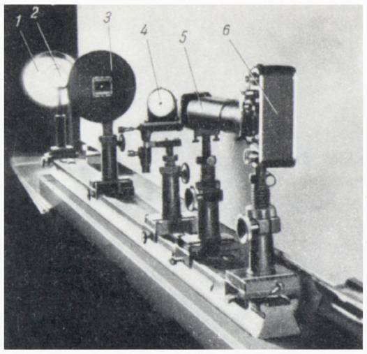
Fig. 5. Installation for observing and photographing diffraction patterns. 1 - lamp, 2 - projecting lens, 3 - precise diffract with light-protective screen, 4 - holder with difrakini lenses, 5 - light-protective tube, 6 - camera without lenses.
In optics, they most often deal with the first layer, since the wavelengths of visible light are very short (from 0.7 μm for red light to 0.4 μm for violet light), but at large distances from a small hole or from a thin wire, the second layer can also occur.
The phenomena of light diffraction can be observed using very modest means. Pierce a 0.1-0.2 mm hole in thin foil with the tip of a sharp needle and stick the foil onto a sheet of cardboard with a hole, which is needed so that the light from the source - a regular table lamp - does not interfere with observation. Having placed a sheet of cardboard on a stand, project onto it with a lens with a focal length of 4-6 cm an enlarged image of a lamp hair so that part of the image of the hair falls on the hole in the foil. A light cone is formed behind the hole, which can be easily found by a light circle on the frosted glass or by the eye (when the eye enters the light cone, the hole appears to glow brightly). At a distance of about 0.5 m from the hole, we will place objects in the light beam, and we will observe the diffraction pattern at a distance of also about 0.5 m behind the object. Observation should be carried out through a weak lens with a focal length of 2-5 cm, mounted on a stand, and the eye should be placed at such a distance from the lens that it is always brightly illuminated. Against a light background, the diffraction pattern will be clearly visible.
figure 5 shows a photograph of the installation in which all the diffraction patterns included in this article were obtained. An optical bench was used, which, of course, is not necessary; for strengthening objects with any tripods with screw movements, it will be much easier to bring the diffraction pattern to the center of the field of view.
The shadow from the straight edge of the opaque screen gives you the edge of a safety razor. From two blades you can make a gap 0.3-1 mm wide. A piece of wire up to 1 mm in diameter will demonstrate diffraction from a narrow screen. The diffraction from the tip of the needle looks interesting.
To observe a light spot in the center of the shadow of a round object, take a steel ball from a bearing with a diameter of 2-4 mm. Using a drop of glue, glue the ball to the glass plate. (It is necessary to ensure that the glue does not protrude beyond the contour of the ball, and that the surfaces of the glass and the ball are clean.) When the glue dries, attach the plate with the ball to the installation. Moving the plate, bring the shadow of the ball to the center of the field of view. In this case, both the external diffraction rings and the spot in the center, surrounded by dark and light rings, will be clearly visible.
You will probably want to photograph the diffraction patterns. This is easy to do if you use a camera with the lens screwed out. Shadow from object
45
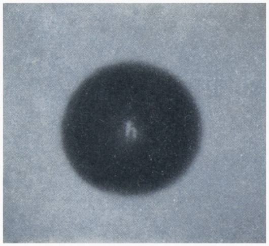
Fig. 6. Photograph taken using a ball. External stakes are placed. Ball diameter 4 mm. Symbol height 1 mm. The range was obtained by photographing a letter drawn in ink on white paper on a contrasting film.
projected directly onto the film plane. In order for the diffraction fringes in the photograph to be clearer and their number to be greater, the responsible ones, serving as a light source, must be covered with a light filter, the best red ones, since there are many red rays in the spectrum of an incandescent lamp. For general films, an exposure of 5-10 seconds was sufficient. To avoid exposure of the film, a blackened inner tube must be placed between the device and the object.
Mixing the light source causes the shadow to change, and therefore the spot. Therefore, if you take a range of sizes together with the exact source, then each pronouncing point on it will give its own, slightly mixed shadow of the ball with its own light spot. As a result, the outer diffraction rings are placed, and the range image can be seen in the center of the shadow. The ball will act like a lens. This is how the photograph of the symbol for Planck’s constant (Fig. 6) was obtained.
By drilling a round hole with a diameter of about 2 mm into thin sheet metal, you can observe how the diffraction pattern changes from the round hole at different distances from it. By covering the light source with a light filter and bringing the eye and the moon closer to the answer, starting from a distance of 1-2 m, you will see how black circles appear in the center of the picture, which, as the eye approaches, turn into dark rings, spreading to the edges of the shadow. The number of dark tracks, including the dark spot in the center, is determined by the difference in the light paths for the central beam and the beam coming from the edge of the branch. This can be used to determine the wavelength of light. To make calculations, you need to know the diameter of the branch, change the distance from the light source to the branch and the distance from the branch to the observation plane. The position of the observation plane can be determined by placing a magnifying glass and head in the field of view and moving it until it appears sharp to the eye against the background of the diffraction pattern being studied. The position of the horn determines the plane viewed through a magnifying glass. We will explain below how to derive the calculation formula.
In white light you can observe the beautiful change in color of the diffraction tracks. The colors you see are not spectral colors. They are called complementary and are observed when any one spectral region is removed from the full spectrum of white light. In our case, when, for example, in the center there is a dark spot for evil light, the remaining parts of the spectrum, that is, red-orange and violet, color the center of the picture purple. The absence of red results in a green-blue complementary color, etc. figure 7 shows examples of diffraction patterns from a circular response.
Why does a dark spot appear in the center, where the waves arrive seemingly continuously?
Let’s return to our observations